1-Wire Sensors and Cabling
The diagram below shows the basic design of a 1-Wire sensor network used with the Mini-Monitor system.
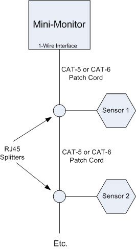
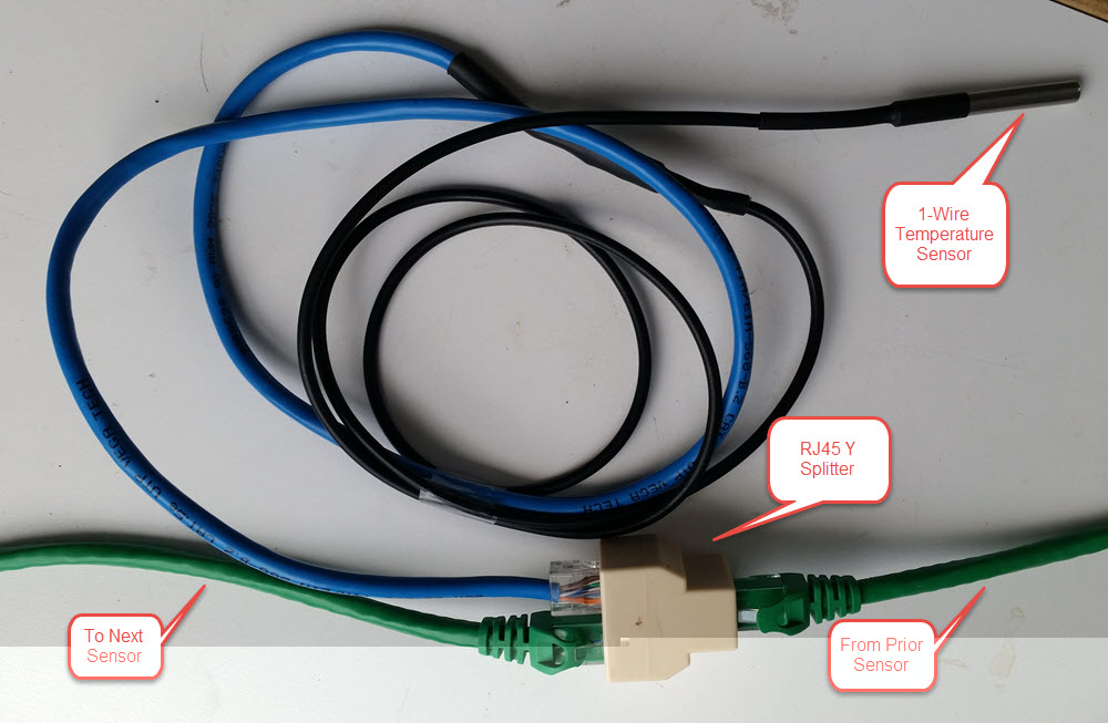
CAT-5/6 patch cables are used to connect the Mini-Monitor to the first sensor, connect the first sensor to the second sensor, etc. At each sensor node an RJ45 Y splitter is used to split the trunk cable off to the sensor. Below is a picture of one node, showing the Green trunking cables and a 1-Wire temperature sensor connected at the node. The cabling from the splitter to the sensor should be kept relatively short, less than 10 feet. Trunk runs can be as long as needed to reach the next sensor.
Selection of the RJ45 splitters is very important. A number of models were tried that had very poor reliability. We discovered that the models that worked reliably have the RJ45 clips oriented the same way on the input and output sides of the splitter. The picture below shows a good splitter, and the clip for the cable on the left is pointed up, and the clips for the two cables on the right are also pointed up.
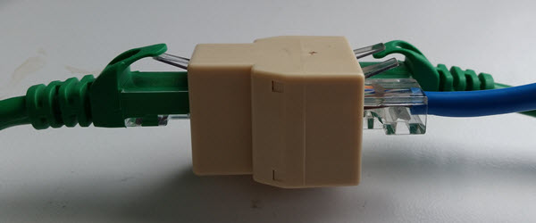
Sources where we found good splitters were:
Amazon From the picture, this model appears to be correct. Return them if the clips are not placed on the same side–really!
1-Wire Temperature Sensors
The Mini-Monitor system software knows how to read 1-Wire temperature sensors using the DS18B20 chip. There are many sources for temperature probes utilizing this chip. For example, here is a suitable temperature probe sold on Amazon. There are numerous suppliers on EBay. Seach for “DS18B20” to find products.
DS18B20 temperature sensors have three leads, these must be soldered to the appropriate wires in the CAT-5/6 cable. The connections, assuming the standard T-568B CAT-5/6 color code, are:
Power/VCC sensor lead -- Orange CAT-5/6 wire (pin 2)
Data sensor lead -- Blue CAT-5/6 wire (pin 4)
GND (ground) sensor lead -- White/Blue CAT-5/6 wire (pin 5)
In the prior picture showing the temperature sensor, you can see the soldered, heat-shrinked, junction between the black sensor cable and the blue CAT-5 cable. The cable terminates with an RJ45 plug for connection to the splitter. We found it easiest to cut a CAT-5/6 patch cable in half to make two sensor cables with RJ45 connectors.
Pre-made sensor probes with compatibly-wired RJ45 connectors are available from iButtonLink.
Each DS18B20 temperature sensor chip has a unique ID. The Mini-Monitor system uses this ID as the Sensor ID it posts to the BMON online sensor database. Before installing a sensor, you should use a 1-Wire software program such as the OneWireViewer to read the ID from the sensor and so you can label the sensor with the ID.
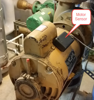
1-Wire Analysis North Motor Sensors
The On and Off events of a motor, pump, zone valve, gas valve, fuel solenoid, or anything emitting a significant AC electromagnetic field can be sensed by an Analysis North 1-Wire Motor Sensor. The Motor Sensor attaches to the target device with high-temperature Velcro. The Motor Sensor cable terminates with an RJ45 connector for connection to the splitter at a 1-Wire node. Here is a picture of Motor Sensor attached to a pump: