Software
This section of the documentation explains how to install and configure the Mini-Monitor software on a Raspberry Pi computer. There are three steps to install and configure the software.
Download, unzip, and write the Image file containing the Mini-Monitor software onto an SD card.
Insert the SD card into a PC and edit the Settings file to configure the Mini-Monitor for your application.
Boot the Raspberry Pi with the SD card, log on, and upgrade the Mini-Monitor software to the newest release. Reboot to begin using the newest software.
Each of these three steps is described in more detail in the following sections.
Download and Install Mini-Monitor SD Card Image
The Raspberry Pi uses an SD card as a solid-state drive for the storage of the operating system, programs, and user data. We have made a complete image of the SD card containing the Raspbian Linux Operating System and the entire Mini-Monitor software application. This image is based on the Raspberry Pi OS Lite image. You can download a zipped version of this image from the link below. The file is about 1.8 GB in size so will take some time to download.
Mini-Monitor SD Card Image (1.5 GB), version 3.9
Use the Raspberry Pi Imager software to write the image to an 8 GB or greater micro-SD card.
GUI Configuration Program
The SD card has a partition that is readable on a Windows PC, Mac, or
Linux computer. On a Windows PC it will show up as a drive labeled boot.
On this partition is a GUI-based setup utility available that can
easily configure Internet access
and a few other key settings. The utility can be run from the Windows PC or the Mac PC
that created the card. The file
name of the utility is settings_editor_win.exe for use on a Windows PC, and
settings_editor_mac for use on a Mac PC. This utility allows for setting up
an ID for the logger, configuration Internet access, and configuring the Utility
meter reader software.
Manually Set up Internet Access
Configuration can also be performed manually by editing files on the boot
partition of the SD card.
Although these files are usable on a Windows PC, they are text files
that use the line-ending format (”n”) used on Linux computers. It is important
to preserve that type of line-ending when editing the files. The
standard Notepad program that comes with the Windows Operating System
does not preserve Linux line endings. Most text editors used for
programming do preserve line endings, such as
EditPlus or Notepad++.
You need to use one of these editors when editing the files described in
this section and the next.
The first issue to address is setting up Internet Access. Here are three possibilities:
Wired Ethernet Internet access through the RJ-45 port on the Raspberry Pi. No special software configuration is needed for this option.
Wireless Internet access either through the built-in WiFi adapter present on the Raspberry 3, or through a USB WiFi adapter plugged into a USB port. For more details on setting up a WiFi connection for the Raspberry Pi, click here.
Internet access through a Cellular Modem connecting to a mobile data network. For certain Huawei cellular modems (models E173u-6, E173s-65, E3276s-500, E3276s-505, and E1756C) connecting to the GCI (Alaska) mobile data network, configuration just involves setting the
USE_CELL_MODEMparameter toTruein the Settings file, and setting theCELL_MODEM_MODELparameter to the correct model type, as described below. For other modems and other carriers, appropriate modification of thepi_logger/wvdial.conffile on the SD card will be required. See documentation of the WvDial program for further information.
If you need to set up a static IP address for the Raspberry Pi, the pi_logger/dhcpcd.conf
is available for that purpose. See
this article .
The appropriate settings lines are at the bottom of the dhcpcd.conf file, but are commented
out by default.
Configure Settings File for your Application
The next step is to edit the special Mini-Monitor Settings file on the
SD card to configure the software for your application. The settings
file is found at pi_logger/settings.py when accessed through the SD card, and
/boot/pi_logger/settings.pywhen actually running on the Pi.
Open this file in a text editor; see the discussion in the prior section regarding the use of a Text Editor that preserves Linux line endings. This file is essentially a Python code file, but the only types of statements in the file are comments (any text appearing after the “#” symbol at the beginning of a line) and variable assignment statements, like:
LOGGER_ID = 'test'
The rest of this section will explain the key variables that can be altered in this file. Excerpts from the file will be shown followed by an explanation of setting. After modifying values in the file, simply save it back to the SD card.
# The unique ID of this particular logger, which will be prepended to
# sensor IDs.
LOGGER_ID = 'test'
Each Mini-Monitor needs to be assigned an ID that is unique across all of the Mini-Monitors posting data to a particular BMON web site. The ID should be kept to 13 characters or less, using only letters and numbers (no spaces). An example is ‘Okla511’, which was used for a building at 511 Oklahoma Street. As shown in the example above, the ID string must be enclosed in single or double quotes.
# The intervals for reading sensors and for logging readings
READ_INTERVAL = 5     # seconds between readings
LOG_INTERVAL = 10*60  # seconds between logging data
The READ_INTERVAL setting controls how often the Mini-Monitor reads
the sensors attached to it. The value is expressed in seconds, and in
general it should be a value of 5 seconds or longer. The
LOG_INTERVAL expressed in seconds determines how often the sensor
readings are summarized and posted to the BMON server. As you can see in
the example above, a math expression can be used, such as 10 * 60. If
READ_INTERVAL is set to 5 seconds and the LOG_INTERVAL is set to
10*60 or 10 minutes, sensors will be read 120 times before their data
is posted to the BMON server. For analog sensors or readings (ex. temperature)
the 120 readings are averaged together before being
posted to the BMON server. A post is timestamped in middle of the 10
minute interval, since the posted value represents conditions occurring
throughout the interval.
For sensors or readings that are state values, such as On/Off readings or perhaps a Fault Code, every change of state that occurs in the 10 minute interval is posted as a separate reading value, appropriately timestamped. The last state recorded in the interval is also posted, even if no change occurred in the interval.
Note that these settings do not apply to separate processes that post sensor data directly to the Mini-Monitor MQTT broker; the settings apply only to the Sensor Reader Classes described in a following section. As an example, the Utility Meter Reader script is a separate process that posts directly to the MQTT broker; it has a separate interval setting found near the bottom of the Settings file and described later in this document.
Sensor Reader Classes
# A list of sensor reader classes goes here
READERS = [
'ha7s.HA7Sreader',             # 1-Wire Sensors
'sage_boiler.Sage21Reader',    # Burnham Alpine Boilers w/ Sage 2.1 controller
#'aerco_boiler.BMS2reader',    # AERCO BMS II Boiler Manager
#'dg700.DG700reader',          # Energy Conservatory DG-700 Pressure Gauge
#'labjack.LabjackTempReader',  # Thermistors connected to Labjack U3
#'sensaphone.SensaphoneReader',   # Reads Node sensors from Sensaphone IMS 4000
'sys_info.SysInfo',            # System uptime, CPU temperature, software version
]
The READERS setting holds a list of sensor reading code segments
that are needed for your application. If you want to use a particular
sensor reader, remove the ‘#’ symbol from the beginning of the line. To
disable a particular sensor reader type, enter a ‘#’ at the beginning of
the line. In the example above, three sensor readers are enabled:
The reader for 1-Wire sensors connected to the Mini-Monitor.
The reader that will collect data from a Burnham Alpine Boiler using the Sage 2.1 controller.
A reader that will report general system information including the amount of time the system has operated since the last reboot, the temperature of the CPU, and the Mini-Monitor software version.
Do not change anything else in this section other than adding or removing ‘#’ symbols from the beginning of reader lines.
More detail is provided on each reader type in the Available Sensor Readers document. That document explains what values are read and reported by the various readers.
Settings related to Recording Transmissions from Utility Meters
# Set to True to enable the meter reader
ENABLE_METER_READER = False

# A Python list of the Meter IDs you wish to capture and post.
# Use empty brackets to read all meters, i.e.:  []
METER_IDS = [1234, 6523, 1894]

# The minimum number of minutes between postings. If you set
# this too low, the resolution of the posted meter reading delta
# will be low.
METER_POST_INTERVAL = 30  # minutes

# The multipliers below are applied to the rate of change calculated from
# sequential meter readings.  They can be used to convert that
# rate of change into engineering units, such as BTU/hour.
# There is a separate multiplier for Gas Meters, Electric Meters and Water Meters.
# *** NOTE: If you set a multiplier to 0, that type of Meter (gas, electric, water)
# will not be recorded by the Mini Monitor.
METER_MULT_GAS = 1000.0       # Converts Cubic Feet/hour to Btu/hour
METER_MULT_ELEC = 1.0         # Electric Meter Multiplier
METER_MULT_WATER = 1.0        # Water Meter Multiplier
These settings are for the script that can receive meter reading transmissions from certain Utility meters. See the Hardware document for the necessary Mini-Monitor hardware. Further discussion of the values posted by this script is available in the Available Sensor Readers document.
The ENABLE_METER_READER setting must be set to True to enable reading of
utility meter transmissions. METER_IDS is a Python list containing
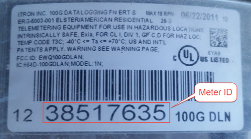
the Meter IDs of the meters you wish to record. You can generally find
the Meter ID number on the meter nameplate, as shown in this picture:
You can also use a METER_IDS setting of empty brackets, [] to
record all meters received by the Mini Monitor.
METER_POST_INTERVAL is the minimum number of minutes between meter
readings that are used to create a recorded/posted value. As explained
in the Available Sensor Readers document, the script posts the amount
the utility meter value has changed, so if this
METER_POST_INTERVAL is too short, a low resolution change value will
be reported.
Finally the various METER_MULT_ settings give multipliers that
are applied to the rate of change value determined by the meter reader
before it is sent to be stored or posted. The meter reader normally
calculates a rate of change per hour; for a natural gas meter that
value usually has the units of cubic feet per hour. Setting METER_MULT_GAS
to 1000.0 then converts the value to BTU/hour, since there are
approximately 1,000 BTUs per cubic foot of natural gas.
If any of the METER_MULT_ settings are set to 0, that type of meter will
be ignored and not recorded.
Upgrade Mini-Monitor Software to Newest Release
Once you have updated the Settings file on the SD card, the next step is to start the Raspberry Pi and upgrade the Mini-Monitor software to the newest version. Insert the SD card into the Raspberry Pi, connect an Ethernet cable with Internet access, and apply power. Then, log onto the Pi either through use of a console cable or an SSH connection. The log on credentials are:
mini-monitor login:  pi
Password:  minimonitor
Change into the main software directory and update the software using a Git source control pull command by using these commands:
cd pi_logger
git pull
If you would like to change the log-in password, use the passwd
command. Reboot the logger to utilize the new software:
sudo reboot
In the future if you need to update the Mini-Monitor software, this same
process should be repeated. Also, for a new update, you should inspect
the /home/pi/pi_logger/system_files/settings_template.py sample
Settings file to see if any new setting variables have been added, which
could require an update of your actual Settings file, as discussed in
the prior section.