Hardware
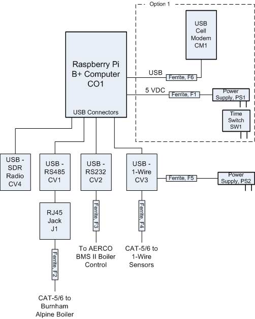
This section of the documentation gives details on the hardware components and interconnection required to build a Mini-Monitor system. The block diagram below shows the main components of the Mini-Monitor system.
Option 1
The Mini-Monitor system needs access to the Internet to post the data collected by the system. There are a number of options available for Internet access including:
Direct Ethernet connection to an existing building network that has Internet access.
Use of a USB WiFi adapter plugged into the Raspberry Pi to access an existing WiFi network.
Use of a cellular data connection to provide Internet access through a mobile wireless network, which is the option shown in the diagram above.
More detailed information on Internet access is provided in the AHFC Building Monitoring System Design Guidelines, Section 3.
The components within the dashed box and labeled Option 1 show the preferred method of providing a cellular data connection to the Raspberry Pi. A USB Cellular Modem is connected directly to a USB port on the Raspberry Pi. Configuration of the Modem on the Raspberry Pi is described in the Software document. Connection tracking software on the Pi combined with a reliable Cellular Modem make for a relatively robust Internet connection. For added reliability, the power to the Pi can be periodically cycled using the Timer Switch (part SW1), which is described later in this document.
The diagram below shows an alternative method of providing a cellular Internet connection to the Raspberry Pi. A cellular router is used in combination with the cellular modem. The router provides a standard Ethernet connection to the Raspberry Pi. This option utilizes more equipment than Option 1 and is therefore more expensive. We have yet to find a cellular router that is both inexpensive and capable of providing a reliable Internet connection. However, Option 2 using a cellular router does offer the advantage of providing a WiFi network for other WiFi-enabled devices such as smart thermostats. Further discussion of this configuration may be found below under the section Part CR1, Cellular Router.
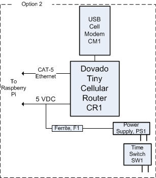
Option 2
The picture below shows an assembled version of the Mini-Monitor using Option 1 with a cellular Internet connection. Not all components present in the block diagram are present in this particular setup. In particular part CV2 which is used to read data from an AERCO boiler is not present, because an AERCO boiler is not present in this building. Also, the some of the clamp-on ferrite cores, F1 - F4, are not present in picture. The two power supplies, PS1 and PS2, are outside of the enclosure, so are not shown in the picture. It is also worth noting that the Mini-Monitor in the picture was constructed with a Raspberry Pi model B computer (part CO1), but new Mini-Monitor installations should use the Raspberry Pi 3 Model B.
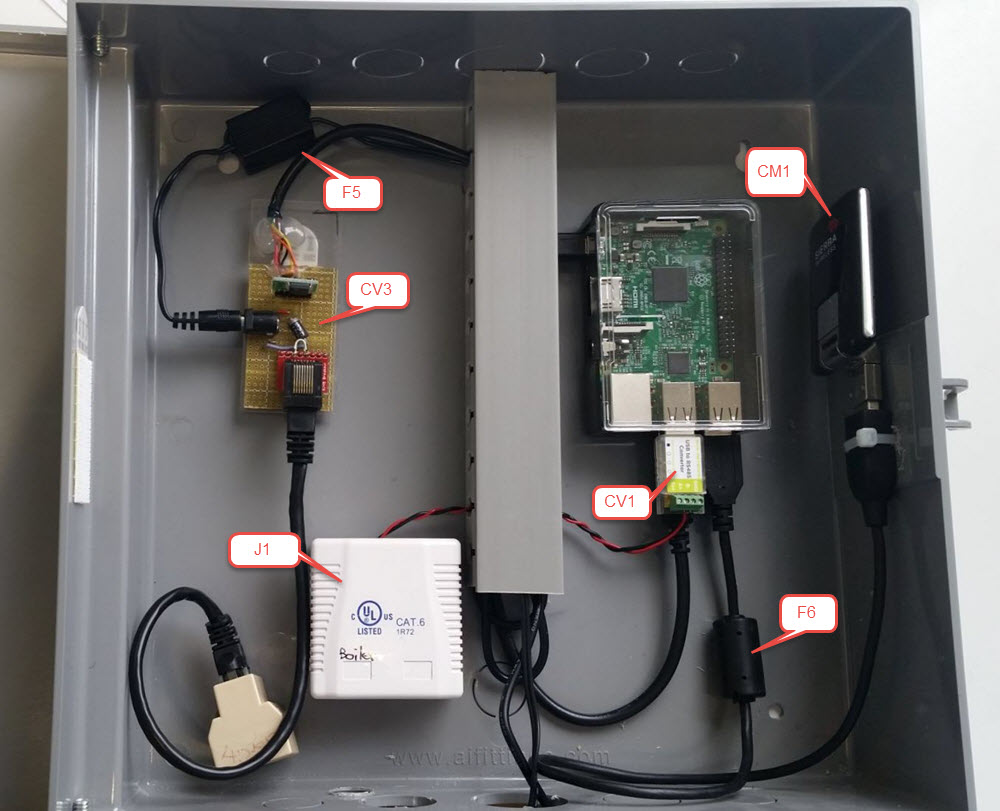
Mini-Monitor configured using Option 1
Below is a picture of the Mini-Monitor configured using Option 2 with a cellular Internet connection involving the cellular router.
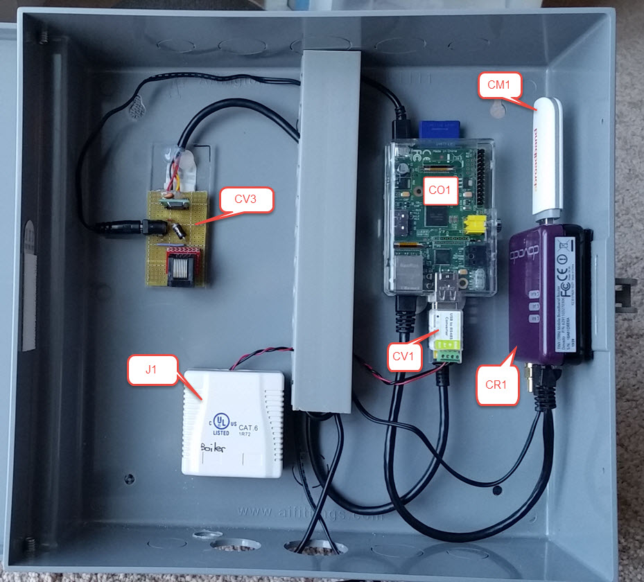
Mini-Monitor configured using Option 2
The rest of this document provides additional detail on the components that make up the Mini-Monitor and provides additional hardware assembly detail. Software configuration issues are documented elsewhere.
Part CO1, Raspberry Pi 3 Model B Computer
This is a small Linux computer, available from many different sources. Here is the product website. For new installations, the Pi 3 Model B should be used, although older models may work with the software.
We have been using a simple plastic case for the Pi, many are available and suitable. The model B+ Pi takes a micro-SD card, and the Mini-Monitor SD card images are meant to fit on an 8 GB micro-SD Card. We have typically used cards made by SanDisk.
GPIO Pins used on the Raspberry Pi
Some of the GPIO pins on the Raspberry Pi have special uses and are not
shown on the above diagrams. Pin 16 (BCM numbering) is used by the
Power Outage Monitor Reader, (see Available Sensor Readers), as
a digital input to sense the presence or absence of AC Power. Pin 12 (BCM
numbering) can be wired through a resistor to an LED to show the general status
of the Mini-Monitor’s Internet connection. The LED will be lit when Internet
is available and will be off when Internet is not available. Internet status
is checked at boot-up and every 10 minutes thereafter by the scripts/set_health_led.py
script, which is run by a Cron job.
Part CM1, USB Cell Modem
Both Option 1 and Option 2 require the use of a Cellular Modem with a USB interface, part CM1 in the above diagrams. The cellular modem is the radio device that communicates with the mobile wireless network and provides a digital interface for that communication.
For Option 1 in the diagrams above, we have the following modems have been tested and work with the default software image for the Raspberry Pi connecting to the GCI carrier in Alaska:
Huawei E173u-6 and E173s-65
Huawei E3276s-500 and E3276s-505
Huawei E1756C (although some versions of this modem did not reliably connect to the cellular network)
As of mid 2017, these modems were available on Ebay for prices ranging from $15 - $40. Other Huawei modems are likely to work, but should support the 850 MHz and 1900 MHz frequency bands for 2G (EDGE, GPRS) and 3G (UMTS, HSPA) service. If the cellular modem supports 4G LTE, it needs to support the LTE AWS Band 4 frequencies, as this is where GCI operates.
For Option 2, we have found the following combinations of USB cellular modems and Dovado Tiny firmwares to be effective:
Huawei E173u-6 3G/2G cellular modem with Tiny firmware versions 7.3.4 operating on the General Communication Inc. (GCI) mobile wireless network.
Sierra Wireless 313U 4G LTE/3G/2G cellular modem with Tiny firmware versions 7.3.4 operating on the General Communication Inc. (GCI) mobile wireless network. We use this modem because we have sometimes found that 2G/3G signal strength was insufficient, and a 4G LTE modem was required. However, under low signal strength conditions, we have experienced lock ups when using this modem with the Dovado Tiny router despite enabling the Dovado Connection Tracker. To remedy this, we have used a clock timer to reboot the Dovado Tiny on a daily basis.
As discussed in the AHFC Building Monitoring System Design Guidelines, the Option Cloudgate cellular router has proved to be more reliable than the Dovado Tiny router and has a cellular modem built in; however, it is physically larger and more expensive.
Part CR1, Dovado Tiny Cellular Router
The cellular router shown in the diagram and pictures above is a Dovado Tiny router. The router requires the use of a separate USB Cellular Modem, which was described in the above section. We purchased the Tiny router from WirelessGear, located in Australia. The power supply shipped with the router is not compatible with US power outlets. We addressed this by sharing the Raspberry Pi power supply, part PS1, with the Tiny router (as discussed later); however, an alternative is to buy a suitable US-configured power supply, such as Super Power Supply AC/DC Adapter Cord 5V 2A (2000ma) 3.5mm x 1.35mm Wall Plug, available through Amazon or EBay. Also, MovingWiFi out of England sells the Dovado Tiny router with a US power supply as an option, but prices have tended to be higher from this source.
For details on configuring the Dovado Tiny router, please see the Configuring the Dovado Tiny Cellular Router document.
Part PS1, Power Supply for Raspberry Pi and Dovado Tiny Router
The Power Supply, part PS1, is used for the Raspberry Pi and the Dovado Tiny Router if Option 2 is being built. As mentioned above, it is also possible to provide a separate power supply for the Tiny router, requiring an extra AC outlet on the surge protector and an additional Ferrite core (discussed later) for further surge protection.
The power supply is a wall plug-in type, as shown in the picture below:
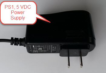
We particularly like this Adafruit 5V 2A power supply because it is designed to put out 5.1 VDC, which is still within specifications for the USB voltage range. Because of the relatively high current draw of the Raspberry Pi and Tiny router, voltage drop occurs between the power supply and the power-consuming devices. By starting at a slightly higher 5.1 VDC, the voltage at the devices will stay above minimum requirements.
In order to share the power supply between the Raspberry Pi and the Dovado Tiny router for Option 2, a Y-splice was made to feed power to both devices. The power connector for the Tiny router was clipped off the Australian-format power supply and spliced into the Adafruit supply cable, as shown in the picture below.
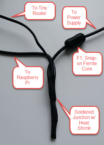
This junction occurs inside the Mini-Monitor enclosure, so one cable extends out of the enclosure to the power supply unit. The snap-on ferrite core is shown in the picture, snapping onto the trunk line back to the power supply.
Parts F1 - F6, Snap-on Ferrite Cores
Mechanical rooms are electrically noisy environments. Providing surge and noise suppression on cables connecting to the Mini-Monitor is helpful to ensure reliable operation. One easy addition to cables that help address this problem are snap-on ferrite core filters. There are five shown in the system diagram above, and they should be mounted in or very close to the Mini-Monitor enclosure.
F1 and F5 fit on the two different power supply cables. The power cables are relatively small, and we use Laird-Signal Integrity Products model 28A0350-0B2 for this application, available from Digi-Key.
The other cables require Ferrite cores with a larger inner diameter. For these applications we use Laird-Signal Integrity Products model 28A2025-0A2, also available from Digi-Key.
Part SW1, Timer Switch
Sometimes cellular modems, cellular routers, or the Raspberry Pi may lock up and fail to continue operating due to software bugs. This generally can be remedied by power-cycling the devices. Timer Switch, part SW1 shown in the above diagrams, is an optional device that can be used to improve reliability if software lock-ups are occurring. The Timer Switch can be programmed to turn Off the Raspberry Pi (and Cellular Modem for Option 2) for one minute and then back On at scheduled intervals. The reboot will generally bring the device out of lock-up. We have found that the following models will perform the task:
Parts CV1 and J1, Burnham Alpine Boiler Interface
If you are collecting data from a Burnham Alpine Boiler using the Sage 2.1 controller, you need to connect parts CV1, a USB-to-RS485 converter, and J1, a punch-down RJ45 jack. The boiler controller has a MODBUS RS485 interface that is accessed through a standard RJ45 jack on the side of the boiler. For CV1, we use the EKM Blink - RS-485 to USB Converter, available direct from EKM Metering or on Ebay. If you choose to substitute a different USB-to-RS485 converter, it must utilize an FTDI converter chip to work with the Mini-Monitor software.
The EKM Blink RS485 converter has screw terminal connections. The cable to the Burnham boiler is a conventional CAT-5/6 patch cable with RJ45 connectors on each end. To allow for an RJ45 connection at the Mini-Monitor, we use a punch down RJ45 jack such as the Monoprice Surface Mount Box Cat6, Single (107092). This is part J1 on the system diagram and Mini-Monitor picture above.
There are two connections required from the EKM RS485 converter to the RJ45 jack: the + connection on RS485 converter goes to pin 8 of the RJ45, and - connection goes to pin 7.
Note the Snap-On Ferrite Core, part F2, should be placed on the CAT-5/6 cable to the boiler.
Part CV2, AERCO Boiler Manager BMS II Interface
If you are collecting data from an AERCO BMS II Boiler Management System, you need to install part CV2, a USB-to-RS232 converter. The model we used is the USBGear USB to Serial Adapter, 9-pin male available from Amazon. If you substitute a different converter, it must use an FTDI chip in order to work with the Mini-Monitor software.
The RS232 converter has a male 9-pin D connector on the RS232 side. Generally, the distance from the Mini-Monitor to the boiler controller is substantial, so we used a CAT-5/6 patch cable to make the connection. To convert the RJ45 connector on the patch cable to the 9-pin connector on the RS232 converter, we used a Cables To Go 02941 RJ45/DB9 Female Modular Adapter available from Amazon. Only 3 pins on the RS232 9-pin connector are used, and the wiring connections are shown below, going from the DB-9 connector on the USB-to-RS232 converter, to the RJ45/DB9 Adapter, to the CAT-5/6 cable, and finally to the AERCO BMS II Boiler Manager screw terminals. Note that the wire colors for the RJ45/DB9 Adapter are specific to the Cables to Go model mentioned above.
DB-9 Pin 3, Transmit from Pi -- RJ45/DB9 Adapter Orange -- CAT-5/6 Orange -- AERCO RXD Terminal
DB-9 Pin 2, Receive to Pi -- RJ45/DB9 Adapter Yellow -- CAT-5/6 Green -- AERCO TXD Terminal
DB-9 Pin 5, Signal Ground -- RJ45/DB9 Adapter Blue wire -- Cat-5/6 White-Orange -- AERCO 232 ISO GND Terminal
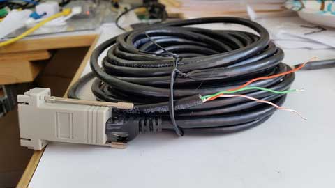
Here is a picture of the CAT-5/6 patch cable with the RJ45/DB9 Adapter at one end and bare wires at the other ready for attachment to the AERCO BMS II screw terminals.
For more information of the RS232 interface of the AERCO BMS II Boiler manager, see the BMS II Boiler Manual. The default RS232 settings for the BMS II are appropriate for use with the Mini-Monitor.
Parts CV3 and PS2, 1-Wire Sensor Interface
1-Wire DS18B20 Temperature sensors and Analysis North 1-Wire Motor sensors can be read by the Mini-Monitor. The Analysis North Motor Sensor attaches via high-temperature Velcro to an AC motor, an AC valve, or other devices that emit an AC electromagnetic field, and detects when the device turns On and Off. For more information on the 1-Wire Bus System, see this Wikipedia Article. To communicate with the 1-Wire sensor network, a USB-to-1-Wire converter or “Master” is required. Three different types were tried, and the most suitable and reliable for this application was a converter based on the HA7S - ASCII TTL 1-Wire Host Adapter SIP. The schematic and assembly of this converter is documented on this page.
If the sensor network includes any Analysis North 1-Wire motor sensors, a power supply, part PS2, must be connected to the CV3 USB-to-1-Wire converter. This power supply supplies power to the 1-Wire sensor network; the DS18B20 temperature sensors do not need the power supply, but the Motor Sensors do. Note, for noise isolation, this power supply must be separate from the supply used by the Raspberry Pi and Cellular Router. The power supply outputs 5 VDC with at least 100 mA of current supplying capacity, the power connector is a 2.1mm x 5.5mm barrel jack (center positive), and a suitable supply is the CUI EPS050100-P5RP. However, almost any regulated 5 VDC supply with the correct connector should work.
The 1-Wire sensors are connected in a daisy chain configuration using CAT-5/6 patch cable and RJ45 splitters to form the network. See the 1-Wire Sensors and Cabling page for important details on the sensors and their interconnection.
Part CV4, SDR Radio for Utility Meter Reading
The Mini-Monitor is able to read Utility meters (natural gas, electric, and water) that utilize the Itron ERT radio transmission format to broadcast their readings in the 900 MHz ISM band to meter readers driving through the neighborhood. The hardware required to receive these transmissions is shown as part CV4 in the System Diagram at the top of this document. This part is a Software Defined Radio utilizing a RTL2832U radio chip and a R820T2 Tuner chip, interfaced through the Mini-Monitor USB port. Examples of this radio device that have been tested with the Mini-Monitor are:
To enable and configure the recording of utility meter readings, certain settings must be included in the Mini-Monitor Settings file.
Surge Protector
For further protection from power quality issues, the two power supplies, PS1 and PS2, are plugged into a surge protector, typically mounted adjacent to the Mini-Monitor enclosure. Unless a third power supply is needed due to not sharing a power supply (part PS1) between the Raspberry Pi and the Dovado cellular router, a two outlet surge protector is sufficient. We use the Tripp Lite ISOBAR2-6 available from Amazon. This model lineup also has a four outlet version available, if needed.
Mini-Monitor Enclosure, Component Mounting, Wiring Channel
Other than the power supplies and the surge protector, the Mini-Monitor components are mounted inside an enclosure with a hinged door. The enclosure we use is the Arlington EB1212-1 available from Amazon. Some of the components come with mounting tape (part J1) or a hook and loop fastening pad (Dovado Tiny). For other components we have found 3M Command Brand Medium Picture Hanging Strips to work well for attachment.
Wiring between components can be organized and provided strain relief through use of comb-type wiring duct. Economical sources can be found on Ebay by searching for “Wiring Duct”.